Blender to POF Conversions
Contents
- 1 Important Wiki Page Links:
- 2 Getting a Collada-capable PCS2 version:
- 3 Recommended Blender DAE Import Settings:
- 4 Importing the DAE into PCS2:
- 5 General requirements for the Blender scene:
- 5.1 Important Note for those who imported an existing FS2 model via DAE:
- 5.2 Orientation:
- 5.3 Scale:
- 5.4 Geometry:
- 5.5 Smoothing:
- 5.6 Textures:
- 5.7 Levels Of Detail:
- 5.8 Nameplates/Cockpit Glass:
- 5.9 Debris:
- 5.10 Single-part Turrets:
- 5.11 Multi-part (rotating) Turrets:
- 5.12 Subobjects/Modeled Subsystems:
- 5.13 Regular Subsystems:
- 5.14 Gun/Missile ports:
- 5.15 Shields:
- 5.16 Insignia:
- 5.17 Docking Points:
- 5.18 Engine Glows:
- 5.19 Glow Points:
- 5.20 Eyepoint:
- 5.21 Esarai's Solution to Unapplyable Empties
Important Wiki Page Links:
POF to Blender Conversions, Blender, POF Constructor Suite 2, Collada Importer
Getting a Collada-capable PCS2 version:
- download The main PCS2 installer package Install this first so you have the correct DLLs in place in your PCS2 directory.
- Dependency 1: The libcollada DLL file Place this in your PCS2 directory.
- The DAE capable PCS2 EXE itself Place this in your PCS2 directory, backing up the previous one if you like. (Old link, Optional)
- Dependency 2: The Microsoft VC2008 SP1 Runtime You might already have this installed from some other program, but if not you'll need this installed too. (Old link, Optional)
Recommended Blender DAE Import Settings:
In Blender, once you are ready to export, go to File -> Export -> Collada 1.4(DAE) and it is advisable to use the following options:

Be aware that selecting the option "Only Export Selected" will cause the Collada exporter to drop all hierarchy information. This will cause extreme pain when importing the DAE file into PCS.
Importing the DAE into PCS2:
Open PCS2, and then go to File->Open and locate your ready-to-open DAE file. Depending on the complexity of your model this could take a fraction of a second to a minute or so. Also remember that once this import is complete, you will still need to save the POF file somewhere, and it is during this part of the process that most errors occur. It is strongly advised that you do not begin adding POF data to a converted model until after it has successfully saved as POF first.
General requirements for the Blender scene:
Important Note for those who imported an existing FS2 model via DAE:
Unfortunately due to a bug in the import script in Blender, imported DAE models are always imported into a new scene, but during DAE export only the first scene is looked in. The fix is an easy one - see POF to Blender Conversions#Correcting for the Blender DAE Importer's slight bug: for more information.
Orientation:
For those who can understand it:
- Stern to Bow axis = Freespace Positive Z axis = Blender Positive Y axis
- Starboard to Port axis = Freespace Positive X axis = Blender Negative X axis
- Belly to Topside axis = Freespace Positive Y axis = Blender Positive Z axis
For those who don't:
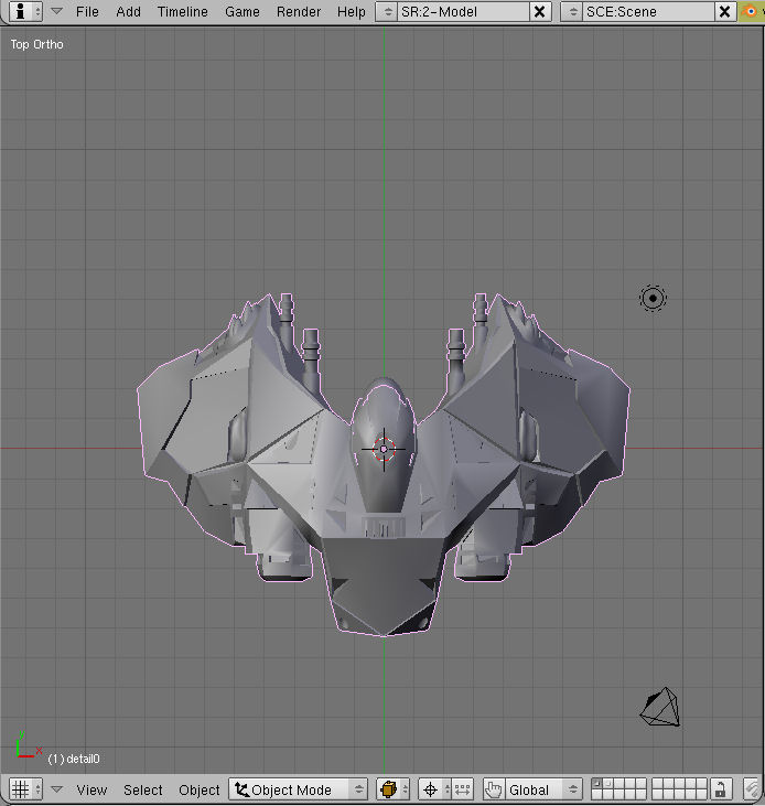
- Go to a top down view of the scene with Numpad-7. You should be looking down at the topside of your ship, with the ships bow pinting up your screen.
Scale:
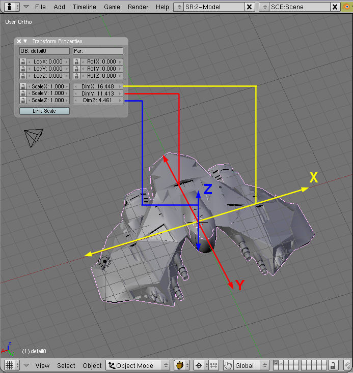
1 Blender unit = 1 Freespace meter, so scale your model to the exact in-game dimensions you want it to be.
To do this, press N to bring up the Transform Properties window and pay attention to the DimXYZ section bottom right. Those are the dimensions of the selected object in Blender units.
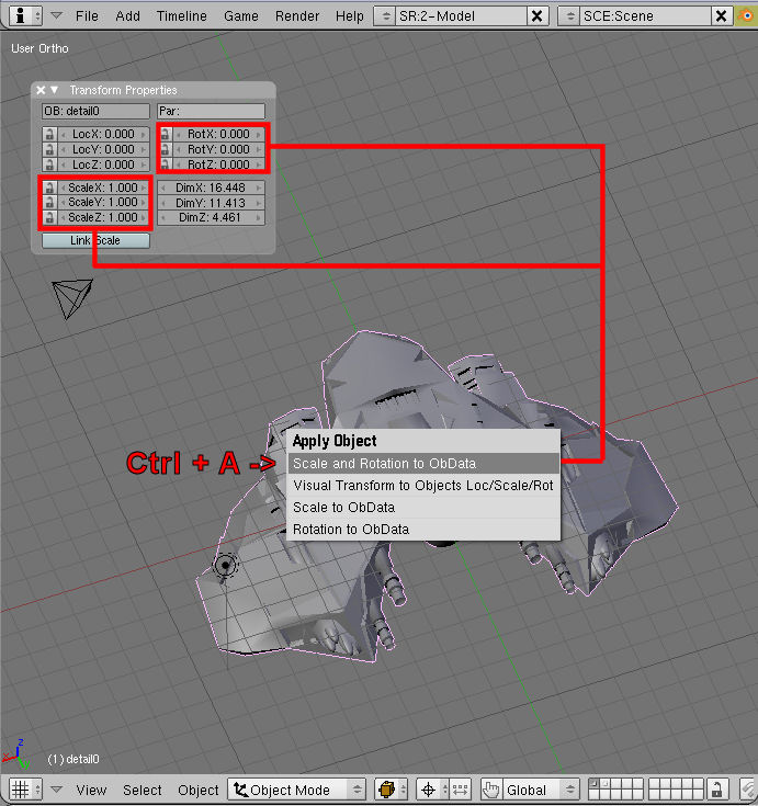
To avoid potential problems with scale and orientation during conversion, you want the RotXYZ and ScaleXYZ fields to read 0,0,0 and 1,1,1 respectively - which you can achieve by pressing Ctrl+A->"Scale and Rotation to ObData" for the selected objects. Doing this will basically hold that object still while setting those fields to 0s and 1s.
Geometry:
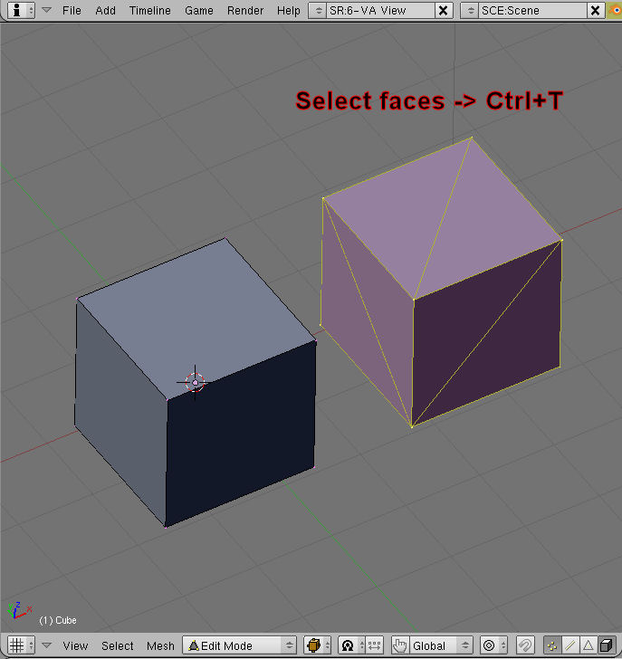
As far as I have been able to tell, all geometry the PCS2 Collada importer will accept must be fully triangulated. (Ctrl+T to triangulate selected object)
All mirror or edgesplit modifiers must be applied before exporting or they won't work and you'll end up with half your model or something. ;)
Messy geometry will usually convert correctly anyway, but I would suggest making it a point of pride to produce clean meshes that will definitely convert. That is, avoid:
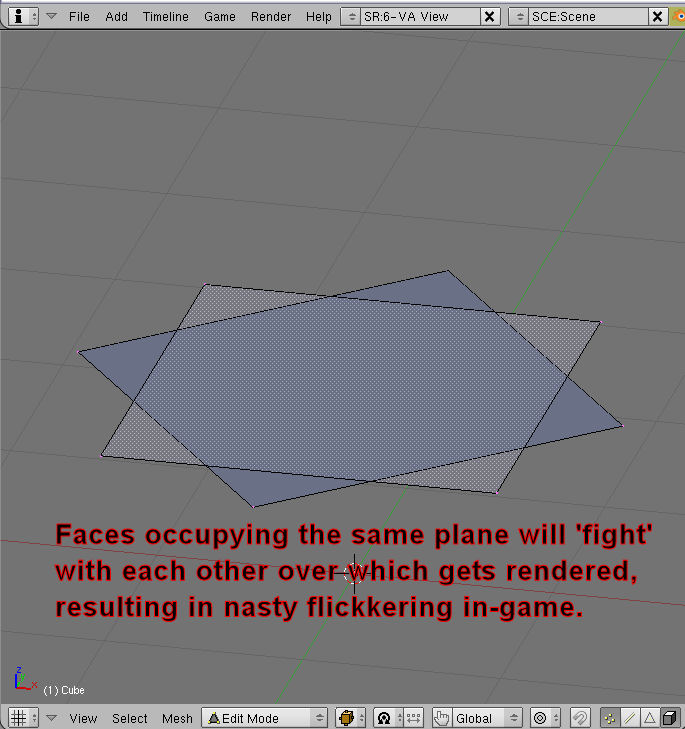
Faces that occupy the same plane in 3d space, as this will cause bad Z-fighting in-game
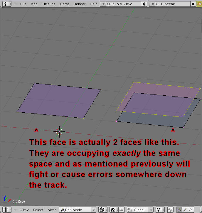
Faces that exactly overlap onto each other
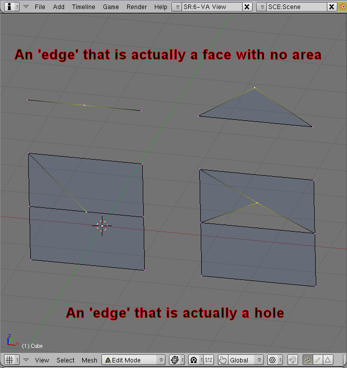
Faces that are formed between 3 verts in a row (ie, 0 area faces)
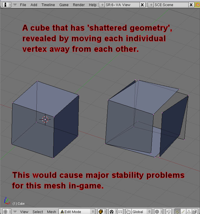
Shattered faces where all or parts of a face are completely detached from surrounding geometry for no good (eg, smoothing) reason.
An excellent error checking tool in blender is the 'select non-manifold' function, which highlights holes in the mesh. To use it, select the object you wish to investigate, enter edit mode and toggle A until you have nothing selected. Set your mode to edge mode (Ctrl + Tab->'Edges' or press the edge icon at the bottom of the 3d View panel) and go to the Select menu in the 3d View panel and click Non-Manifold. All edges that form the perimeter of a hole will be selected, so you can identify areas that should be repaired.
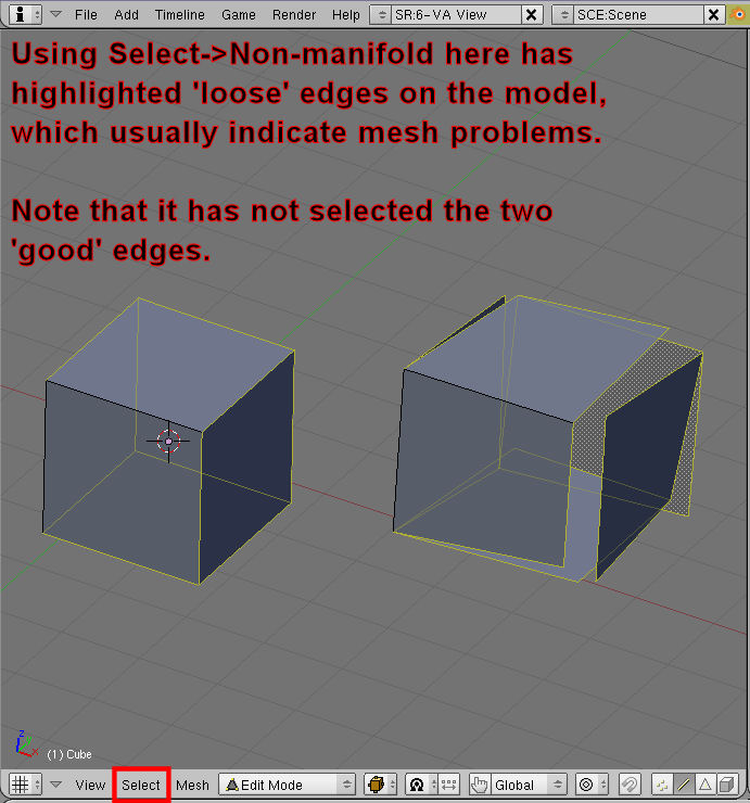
Note: When used with the mirror modifier, this function will select all the edges that form the place where the mirrored side will attach to the 'real' side. This is normal so don't worry about it there.)
A quick point here on the usage of the mirror modifier:
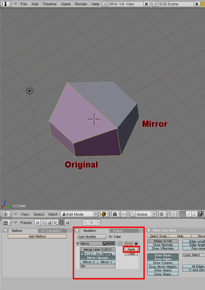
Basically the modifier will create a mirrored copy of your selected object, and will mirror it about that objects centre on the axes you select.
Smoothing:
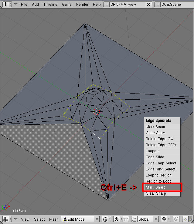
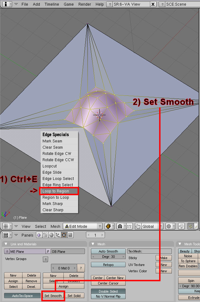
Blender does not use smoothgroups as they are seen in other modelling programs, but it has something pretty close and just as effective. It involves a Three-stage process:
- Select the edges that will make up the perimeter of the area you want to be smoothed (ie, the area you want to become a single smoothgroup) and press Ctrl+E->'Mark Sharp'.
- Use Ctrl+E->'Loop to Region' to select the faces that are inside that perimeter and set them to be smoothed by either the 'Set Smooth' button in the editmode button panel or Ctrl+F->'Shade Smooth'.
- Outside of edit mode, add an Edge Split modifier set only to 'From Marked as Sharp'.
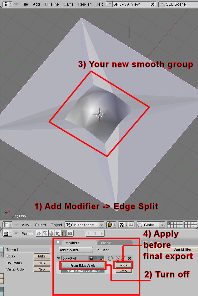
If you apply this modifier before the final export, these smoothgroups will survive the conversion intact and can GREATLY enhance the apeal of an in-game model.
Textures:
The PCS2 Collada importer will read textures from whatever images are assigned to each face of an object in Blenders UV editor (NOT from the materials button panel!)
As such, assuming you have UV mapped the model and have an associated texture ready, select all the faces of the model that use that texture and in the UV/Image Editor view open up that image. (If it's loaded already it will be in the drop down list, if not go to Image->Open)
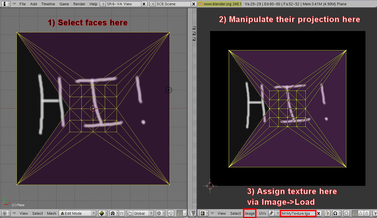
Format-wise, FS can accept TGA, PCX, JPG and DDS. However it is VERY highly recommended (almost a requirement) that you use DDS formats for final releases due to their efficiency. For more information about textures and their usage, see Texturing#Texture Types
Levels Of Detail:
LODs are lower detail duplicates of the main mesh used when the ship is so far away from the player that rendering it at full detail would be a big waste of your graphics card's resources. While not a requirement (FS will work fine without them), it's standard practice to include at least two lower LODs as well as the main hull.
The main lod object should be named 'detail0' (case sensitive), first LOD 'detail1' second 'detail2' and so on. Don't use more than 4 LODs in total as the LODs themselves will become a waste of memory.
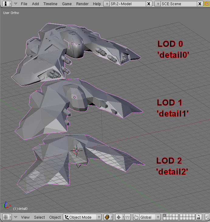
These LODs should not be parented to any other object as they're basically the top of the hierarchy of the model. Also, they should all have their object centres set to the origin of 0,0,0.
Example:
detail0
  |-<subobjects of detail0>
detail1
  |-<subobjects of detail1>
detail2
  |-<subobjects of detail2, though by this stage there shouldn't be any>
Nameplates/Cockpit Glass:
Transparent objects are handled quite badly by FSO at the time of writing, and so the following technique is basically a hack to get around that.
If you have anything that requires transparency as a part of the hull or any subobject, you must:
- Select all faces that will need to be transparent. (For cockpits this means all the polys that would be the glass, and for nameplates it means just the floating nameplate rectangle polys)
- Detach these faces from the mesh they're a part of so they form their own mesh.
- Assign them the texture if nessecary. (For cockpit glass just give it any old image called 'glass' and for nameplates give it any old image called 'nameplate'. Both these textures exist in the 3.6.10 MediaVPs and so will be used on your model with no further worry about it. If you need some other form of transparency you'll have to make your own transparent texture and use that.)
- Name the object in the form of '<Object the transparent polys came from>-trans'. So for example, the glass or nameplate would be called 'detail0-trans', because they were pulled off the main hull.
- Parent the transparent polys object to whatever object they originally came from. (Select the transparent object, then the parent object and press Ctrl+P->'Make Parent' ) For glass or a nameplate this would of course be detail0.
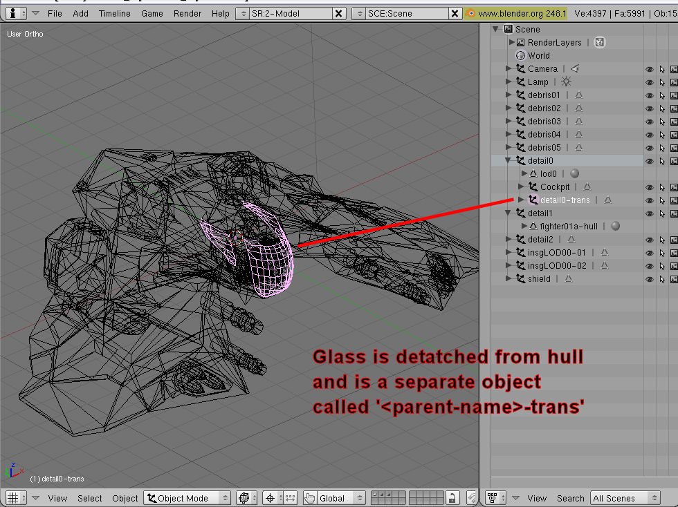
What basically happens is that PCS2 will re-attach the transparent polys to their parent object last in the list, which lets Freespace draw them last of all and so correctly transparent.
Example:
detail0
  |
  |-radardish
  |   |
  |   |-radardish-trans
  |
  |-detail0-trans        (nameplate)
Debris:
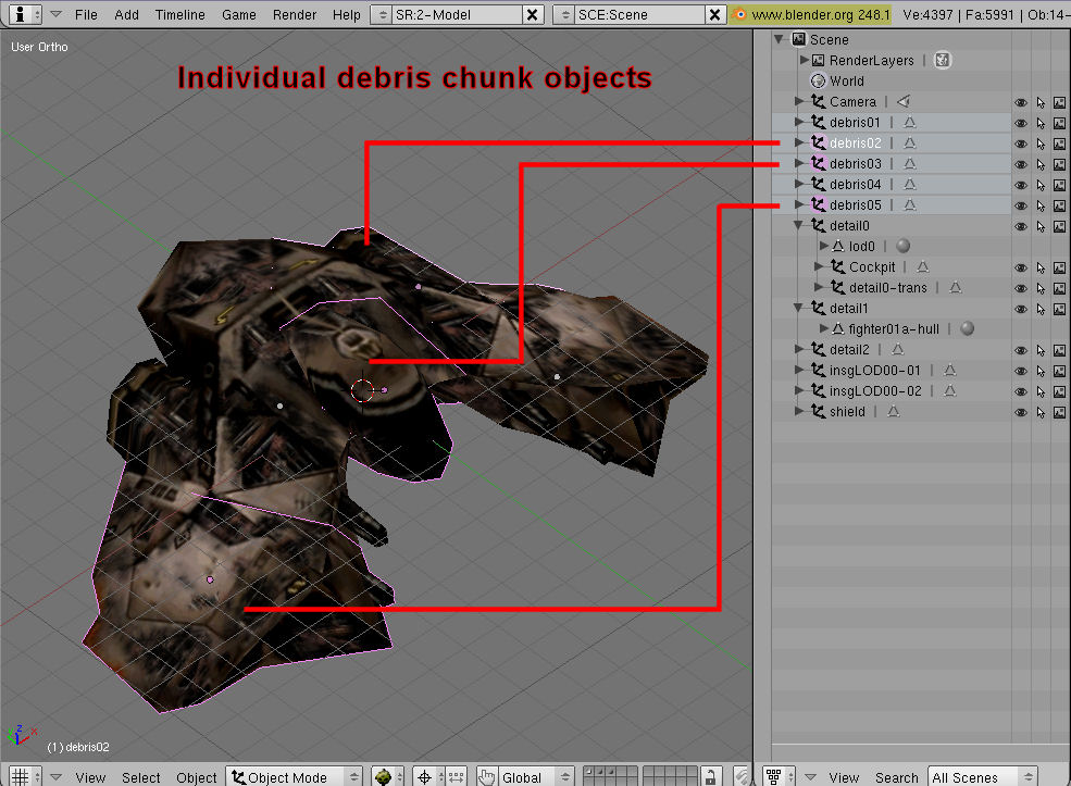
Debris chunks are the pieces that hurl themselves in all directions when a ship explodes. A ship that has no debris will have nothing left at all when it explodes which is really boring! I would recommend constructing full-ship-volume debris for the best explosion effects, as it means that when it explodes the ship essentially just cracks apart and drifts off, which looks much cooler than nothing or a piece here or there.
Anyway, to make debris objects ready for conversion they should be named 'debrisXX' where XX starts at 01 and can go up to 99, though typically any more than about 20 is excessive..
Example:
detail0
detail1
detail2
debris01
debris02
debris03 etc
Single-part Turrets:
All turrets should be named with the word 'turret' or 'gun' in them so FS knows to treat them differently to normal subobjects. Beyond that they can be called whatever you like, though standard practice is just 'Turret01', 'Turret02' etc.
NOTE: Many people myself included much prefer to set up turret firepoints, paths and properties in PCS2 after the conversion, where it's a bit easier and less likely to break during conversion.
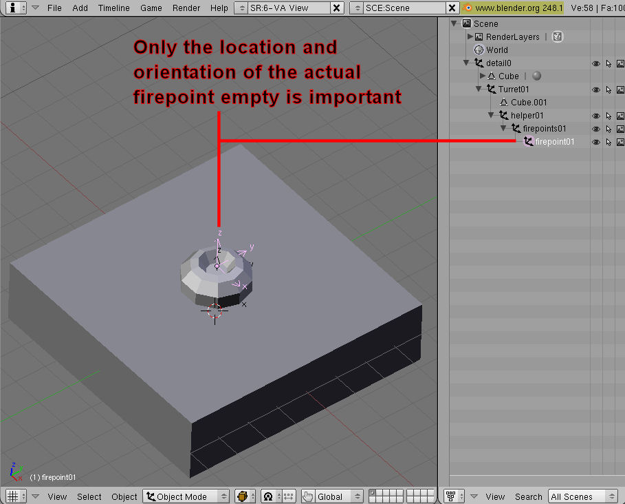
To set up the firepoints of a turret in blender, you'll need to use Empties (also known as helpers). (To create an empty, just press Ctrl+A->'Empty' ).
The basic layout for empties is to have a parent empty attached to each subobject, and then several empties attached to it for things like firepoints, path and properties, looking like this:
It should be noted that when making a ship with more than one turret in Blender, you will need more than one Empty object named "firepoint01." Because of how blender handles duplicate objects, it is impossible for it to have two objects with the same name, and as such pastes a .xxx (object.001, object.002, and so on) on the end of the object name to keep them separate. This additional tag is nothing to be worried about, as the system will disregard anything past the '.' .
Example:
detail0
  |
  |-turret01
  |  |
  |  |-helper01 (NOTE: This top level empty must begin with the word 'helper' ALL NAMES ARE CASE SENSITIVE!!!!)
  |    |
  |    |-firepoints01
  |    |  |
  |    |  |-firepoint1       (NOTE: The orientation of these empties is important - the turret will fire down their Z axis)
  |    |  |-firepoint2
  |    |
  |    |-path07              (NOTE: path and properties are probably best left off and done in PCS2)
  |    |  |
  |    |  |-Path07-01
  |    |  |-Path07-02
  |    |
  |    |-properties01
  |       |
  |       |-$fov=180
  |       |-$name=laser_turret
  |       |-$special=subsystem
  |
  |-turret02
     |
     |-helper02              (NOTE: The number after 'helper' is really just there for your own organisation)
       |                     (ie. helper02 is for turret02)
       |-firepoints02
       |  |
       |  |-firepoint1.001   (NOTE: the .001 part is just there to keep each object name unique in Blender)
       |  |-firepoint2.001   (The importer will disregard everything after the '.' so don't worry about it)
       |
       |-path08              (NOTE: Each turret will require it's own approach path, but these can be generated in PCS2)
       |  |
       |  |-Path08-01
       |  |-Path08-02
       |
       |-properties02
          |
          |-$fov=180.001
          |-$name=laser_turret.001
          |-$special=subsystem.001
Multi-part (rotating) Turrets:
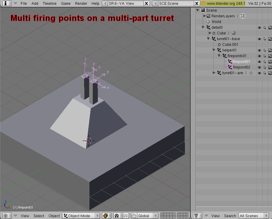
Multi-part turrets consist of two parts: the Base and the Arm. Since the arm needs to inherit the rotation of the base it's attached to, you need to parent it to the base (ie, select arm, base and press Ctrl+P->'Make Parent' ). Note that each turret can only have ONE arm object, but within that object you might have three separate pieces of geometry or so to form three barrels. The turret base should be parented to the LOD it is associated with - typically detail0.
As multi-part turrets need to rotate in-game, they need to have careful attention paid to where their object centres are, or they could spin right off the ship or something equally stupid looking. Place the centres at the points where each piece (arm and base) of the turret would pivot around. Turrets on the topside of the ship must face forwards while turrets on the belly must face backwards.

All turret arms must point straight up out of their base or they will not rotate correctly.
As with single part turrets, the naming must include 'turret' or 'gun' in it somewhere so FS knows to treat it differently, and standard practice is to call the base 'Turret01-base' and the arm 'Turret01-arm'. Also again it is easier to set up turret data in PCS2 after conversion (Setting the turret axis rotation MUST be done in PCS2 in the subobjects field after conversion or else your turrets won't work at all)
Setting up firepoints, paths and properties in Blender is the same as for single part turrets..
Example:
detail0
  |
  |-Turret01        (single part turret)
  |
  |-Turret02-base
      |
      |-Turret02-arm
      |
      |-helper02
         |
         |-firepoints02
         |   |
         |   |-firepoint02-01
         |   |-firepoint02-02
         |
         |-path07
         |   |
         |   |-path07-01
         |   |-path07-02
         |
         |-properties02
             |
             |-$fov=180
             |-$name=main%turret      (The % will be converted to a space automatically)
             |-$special=subsystem
Subobjects/Modeled Subsystems:
These are just done like single part turrets if they don't need to rotate and like multi-part turrets if they do (like radar dishes). You can have an empty system as with turrets if you like, but again this is better done post-conversion.
To make destroyed models for modeled subsystems or turrets, create a model of the wrecked subsystem and put it in the position it will be in when that subsystem is destroyed. Name it '<Subobject name>-destroyed' and Freespace will only make it appear when that subobject has been destroyed. Ie, 'Turret01-destroyed'.
As with rotating multi-part turrets, rotating subobjects axis rotation must be set up in PCS2 after conversion.
Example:
detail0
  |
  |-radardish
  |-radardish-destroyed
Regular Subsystems:
Subsystems are done by placing empties, and then scaling them up to the diameter of the desired subsystem. As with turrets, they can have their properties of '$special=subsystem' added (in the same hierarchy - ie, children of the helper, as seen with the turrets) either in Blender or preferably in PCS2 after conversion.
To name them correctly, simply call them 'subsystemcommunications' or 'subsystemweapons' etc. Subsystems should not be children of anything.
Example:
detail0
detail1
detail2
subsystemweapons
  |
  |-helper
     |
     |-path03
     |   |
     |   |-path03-01
     |   |-path03-02
     |
     |-properties
        |
        |-$special=subsystem
Gun/Missile ports:
For fighters and bombers, you can set up gun and missile points by creating empties representing the gun/missile banks, with children empties representing the individual firing points contained in that bank.
So for example, you would have the parent empty 'gunbank01' with children 'gunbank01-01' and 'gunbank01-02' representing the locations and orientations (down the emtpies' Z axis) of the two individual firing points in that bank. Gun and missile banks should not be children of anything.
Example:
detail0
  |
  |-gunbank01     (This will create a gunbank with two firepoints on it)
      |
      |-gunbank01-01
      |-gunbank01-02
Shields:
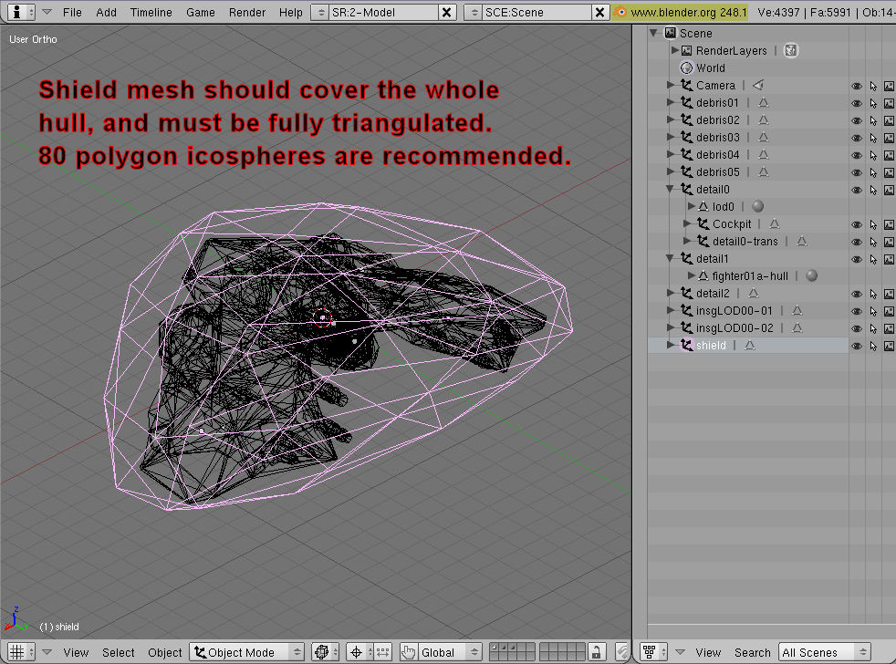
Shields are usually made of only 80 polygons and must be fully triangulated, enveloping the entire model. Name the object 'shield'. Shields should not be children of anything.
Example:
detail0
detail1
detail2
shield
Insignia:
Squadren Insignia should be treated similarly to nameplates in terms of making them on a set of faces that floats just above the hull.
UV map them and apply a texture called 'insignia' (it's a good idea to use an actual insignia texture here, but the NAME is important because the Collada importer in PCS2 will know to ignore it and not put it on the texture list for the ship), and call them: 'insigLODXX-YY', where XX is the LOD number and YY is the number of this particular insignia (for if you have more than one). As the XX indicates, you can create insignia that will appear on LODs too, which is a good idea or else in-game your insignia will suddenly vanish when the ship moves away and the LOD clicks over.
Insignia should not be children of anything.
(Note: The following image was taken when the key phrase was 'insg' rather than 'insig' as it is now. Use 'insig' not 'insg'!)
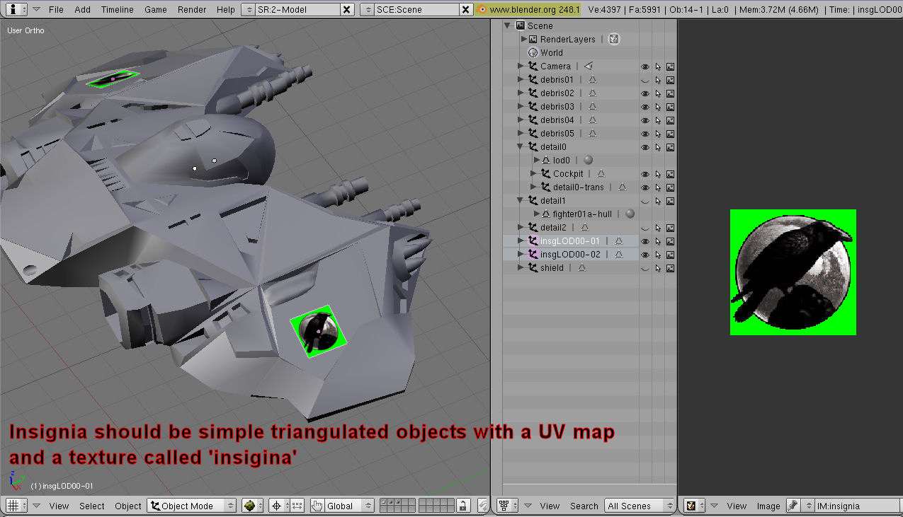
Example:
detail0
detail1
detail2
insigLOD01-01       (This and the one below will actually be assigned to detail0. The two last ones will be assigned to detail1)
insigLOD01-02
insigLOD02-01
insigLOD02-02
Docking Points:
Docking points consist of two individual docking points, an associated path and properties. You can do all of this in PCS2 after conversion where it's a lot easier, but if you really want to you can do it in Blender too:
Make two dockpoints ('dockpoint01-01' and 'dockpoint01-02') the children of a parent 'dockpoint01' empty (which should not be the child of anything). The first point is the location and outwards normal of dockpoint01, and the second defines the 'front' of the dockpoint so that docking ships know which end is the front of the ship.
Dockpoints can have paths and properties set up as with single part turrets, though dockpoints need 4 path verticies instead of the usual two, and can take the property of '$name=<dockport name>'.
Example:
detail0
detail1
detail2
dockpoint01
  |
  |-dockpoint01-01
  |-dockpoint01-02
  |
  |-helper
      |
      |-path09
      |   |
      |   |-path09-01
      |   |-path09-02
      |
      |-properties
      |   |
      |   |-$name=DockingPort
Engine Glows:
These can be done in one of two ways:
- Just basic thrusters involves an empty called 'thrusters' representing the glow bank, and children empties that represent the location and scale of the individual thruster glows. Here 'thrusters' should not be the child of anything.
Example:
detail0
detail1
detail2
thrusters
  |
  |-thruster01-01
  |-thruster01-02
- Linked to an engine subsystem. Here the setup is the same as in 1), but 'thrusters' is set as the child of the helper of the engine subsystem that is meant to be providing these particular engine glows. This way, when that particular engine subsystem is destroyed, only the glows linked to it are removed.
Example:
detail0
detail1
detail2
subsystemengine
  |
  |-helper
      |
      |-path04
      |   |
      |   |-path04-01
      |   |-path04-02
      |
      |-properties
      |   |
      |   |-$special=subsystem
      |
      |-thrusters
          |
          |-thruster01-01
          |-thruster01-02
Glow Points:
These involve a parent empty that must begin with the name 'glowbank', and be the child of whatever subobject the glowpoints are attached to. Any children of 'glowbank' will define the location and scale of individual glowpoints. They also use a helper->properties setup as seen previously, taking only the texture name the glowpoint to be drawn there in-game, such as: 'properties'->'$glow_texture=yellowglow'.
Blinking settings can only be done in PCS2 after conversion, and in fact the entire glowpoint making process can be done there too.
Example:
detail0
  |
  |-helper
      |
      |-glowbank01
      |   |
      |   |-glowpoint01-01
      |   |-glowpoint01-02
      |   |-glowpoint01-03
      |
      |-glowbank02
          |
          |-glowpoint02-01
          |-glowpoint02-01
Eyepoint:
The eyepoint can again be done after conversion, but in Blender it is handled simply with a lone empty named 'eyepoint01' that is not the child of anything. The Z direction of the empty indicates the direction it's facing in.
Example:
detail0
detail1
detail2
eyepoint01
Esarai's Solution to Unapplyable Empties
Occasionally, Blender experiences a glitch where its program-defined 'Empty Object' cannot be applied. Applying an object is done by pressing ctrl+a. It makes the current scale of the object 1 on all axises, and sets its rotation to 0 on all axises. Occasionally, Blender fails to set the rotation to 0 and the scale to 1 after pressing ctrl+a, causing those values to be carried into the dae file. PCS2 treats the current orientation of an object as it's original orientation, and then applies any rotation or scaling data to the object, causing all objects to be scaled and rotated twice as much as they should be. If you notice this occurring with empty objects, you must ensure you are modeling all parts of your ship at the dimensions and rotations they are supposed to appear with in-game (this can be problematic for ships greater than 3 km in length as Blender will have trouble occluding faces not visible in the 3D view, making selecting the appropriate face difficult). These issues can be avoided by creating a stand-in for the empty objects. To do this, create a new mesh object. What kind of object does not matter. Create it and delete all geometry data within the object (enter editmode, select all vertices, and delete them. The object will appear as a pink dot now). This object, while not technically an "empty object," can function as one, and can always be applied.
Just as an example: Say you were to rotate a cuboid turret 45 degrees about the z-axis, select the whole turret setup and associated helper hierarchy and press 'ctrl+a' to apply it. You'll know you are encountering this glitch if the turret now has zero angle rotation on all axises and the scale has been reset to 1, but the helper Empties still have non-one scale and/or non-zero rotation values. In PCS2, these values will be applied to the helpers, and your turret firepoints may end up several kilometers from the weapon barrels.
